Overview
This page details MiRo's geometry, dimensions and conventions, which are used in translating between MiRo's signal interfaces and its physical components.
Coordinate system
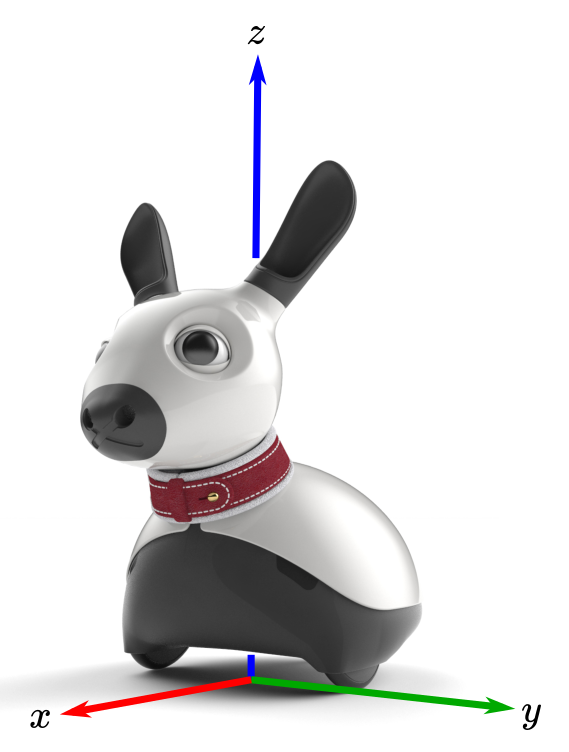
MiRo uses a right-handed coordinate system, as shown in the image. Units are metres and Radians.
Kinematic Chain
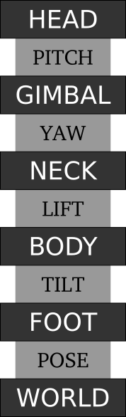
MiRo has three internal "kinematic"[1] degrees-of-freedom (DOF), which are denoted LIFT, YAW and PITCH. These three DOFs connect together MiRo's four physical links (and frames of reference), denoted BODY, NECK, GIMBAL and HEAD. Together, these links and DOFs form the internal kinematic chain.
BODY, in addition, is tilted with respect to the horizontal, by a fixed amount defined by the height of MiRo's rear slider; the corresponding untilted frame is denoted FOOT (footprint), and the fixed "DOF" between them is denoted TILT.
Finally, FOOT is positioned relative to the world frame, WORLD, by the robot's POSE, so that the complete kinematic chain takes the form shown alongside, which has frames (which have a one-to-one correspondence with links) in dark grey and inter-frame relationships in light grey. The table below summarises the fixed parameters of the chain.
| Parameter | Description |
|---|---|
| LOC_TILT_* | Location of tilt joint in FOOT (rotational axis is y). |
| LOC_LIFT_* | Location of lift joint in BODY (rotational axis is y). |
| LOC_YAW_* | Location of yaw joint in NECK (rotational axis is z). |
| LOC_PITCH_* | Location of pitch joint in GIMBAL (rotational axis is y). |
[1] These are known as the "kinematic" DOFs solely to distinguish them from the "cosmetic" DOFs, specifying the position of the cosmetic mobile components (eyelids, ears, and tail).
Configuration and Pose
The immediate state of the kinematic chain is denoted as "configuration" and "pose". Configuration comprises the angles of the four angular relationships and can be represented as a tuple (TILT, LIFT, YAW, PITCH). Pose is the relationship between FOOT and WORLD in the 2D plane, and can be represented as a tuple (x, y, theta).
To determine the state of the chain, the configuration can for some applications be read directly from the corresponding sensor topic sensors/kinematic_joints. Pose, however, is not available from the robot. Estimating pose can be approached in different ways, and these have been the subject of huge research effort in robotics. One way, for example, is to integrate the robot's odometry which is available at sensors/odom.
Main wheels
The table below summarises the geometric parameters of the wheels.
| Parameter | Description |
|---|---|
| WHEEL_DIAMETER_M | Diameter of main wheels (m). |
| WHEEL_TRACK_M | Track of main wheels (m). |
| WHEEL_MAX_SPEED_M_PER_S | Maximum forward/backward speed (m/sec). |
| WHEEL_M_PER_COUNT | Ratio of metres per count of the optical encoders. |
Cameras
The table below summarises the geometric parameters of the Cameras.
| Parameter | Description |
|---|---|
| LOC_EYE_* | Location of left eye in HEAD (right eye is symmetrically placed). |
| CAM_ELEVATION | Elevation of both cameras above horizontal plane. |
| CAM_DIVERGENCE | Divergence of each camera from looking "straight ahead". |
| CAM_HORI_HALF_FOV | The horizontal angular half-field-of-view (radians). |
The installed position of the left-hand camera assembly is obtained as follows.
- Start with a camera assembly with its optical centre at the origin of HEAD facing along the +ve x-axis with upright vector along the +ve z-axis.
- Rotate assembly by
CAM_DIVERGENCEaround z-axis to "look more left". - Rotate assembly by
-CAM_ELEVATIONaround y-axis to "look more up". - Translate optical centre to
LOC_EYE_*.
Thus, the rotation corresponding to divergence is around an axis normal to the plane including the optical axes of both cameras, both before and after the rotation, and the upright vector of the two cameras are parallel when installed. Accordingly, a vertical (before lens distortion) line in the left camera image is vertical (before lens distortion) also in the right camera image.
The stereo overlap region at the centreline is equal to 2 × (CAM_HORI_HALF_FOV - CAM_DIVERGENCE). The total horizontal field of view provided by the two cameras is equal to 2 × (CAM_HORI_HALF_FOV + CAM_DIVERGENCE).
Microphones
The table below summarises the geometric parameters of the microphones.
| Parameter | Description |
|---|---|
| LOC_EAR_* | Location of left ear (right ear is symmetrically placed). |
| LOC_TAIL_MIC_* | Location of tail mic. |
The sensor topic sensors/mics provides data from four microphones. The third microphone is located inside the head and is intended to be used for mitigation of self-generated noise. The fourth is located in the base of the tail and can be used to help localise sounds in the forward/backward direction.